Dana 44 Diff Cover

While the carrier was on its way I decided that I would try to make a new Diff Cover for he Dana 44 axle. I had searched previously to find a DXF file with good enough dimensions to cut on the CNC Plasma. Since the cover was off and I had time I just created the file myself. I placed the stock cover on my weld table and used a scribe to outline the existing cover and the placement of the holes. Once I was comfortable with the markings, I proceeded to measure and draw it in CAD. The outline was fairly simple, but the holes tend to not be so easy. First off the tolerance of the stock cover was all over the place. So I first cut this into a thin sheet of steel to save on the cost of checking the dimension I took. After an initial trial, I discover that two hole were just far enough off that you could start all the others and just slightly off to start the bolt. On the thicker material I decided the easiest way to fix this was to open the hole size up to .375 from .34 and all the bolt fit with out an issue.
After I got the ring to fit I went on to creating the center section. This section runs over the center of the ring gear parallel to the axle center line.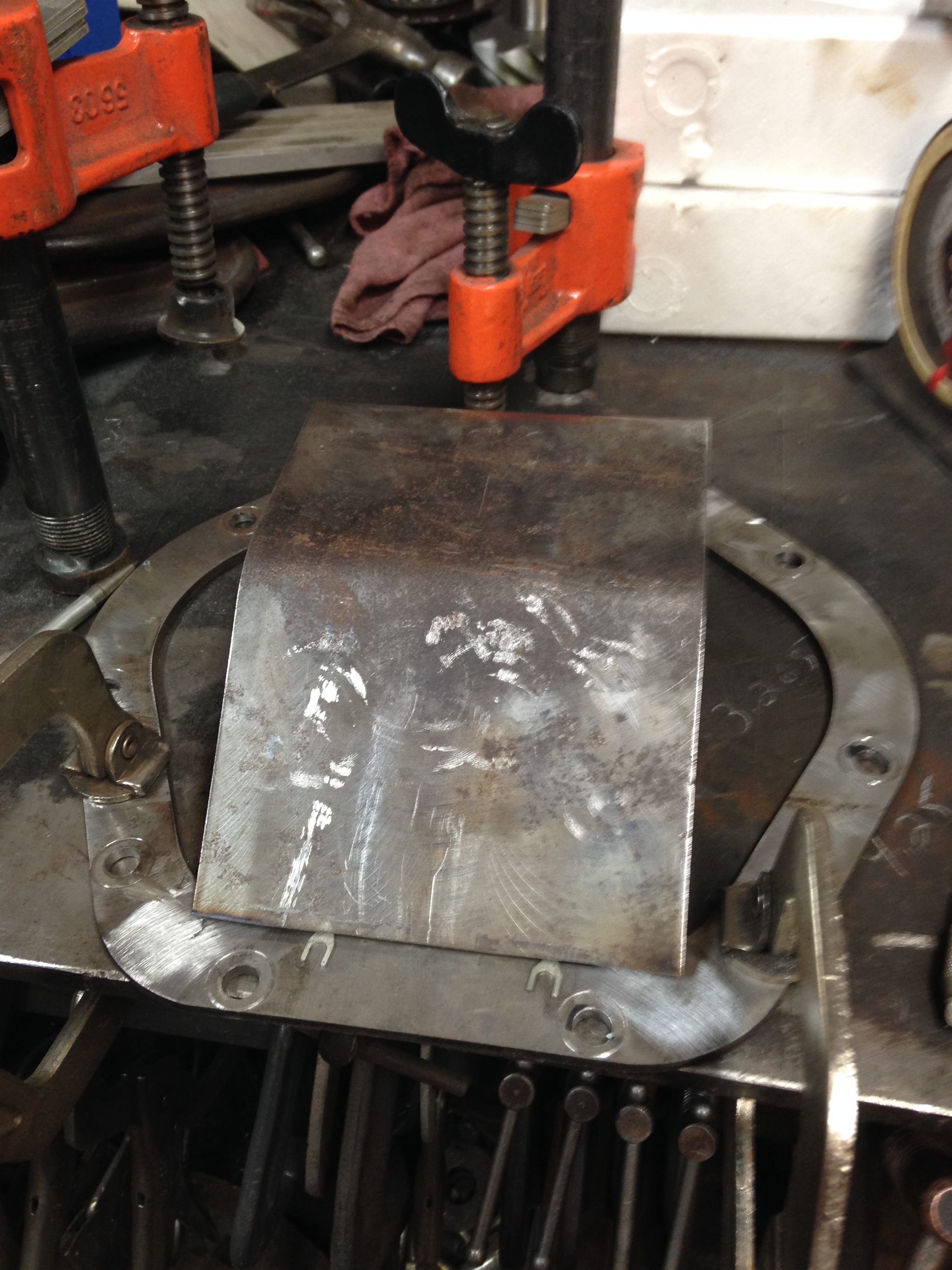 I was able to bend this section over the end of the table with a little persuasion with a sledge hammer. Not the best way, but it is the cheapest to do. To make sure I had enough room for the ring gear to not hit the inside of the cover I had to take some accurate measurements. Since all of my precision tools are not at home this proves to be easier than ever. I used a depth micrometer to measure from the cover surface to the bottom of the bearing surface with the carrier out. This distance was ~3.45″. Since a Dana 44 ring gear is 8.5″ in diameter and the outside of the bearing was ~3.265″, this gave me a distance of ~2.43″ from the surface of the cover to the inside of the cover. I left an additional .1″ to make sure there were not any errors in my measurements. I needed to make sure i was as close as I could be so my drag link would not hit it like it did with the stock cover. Even after the stock cover was massaged with the same sledge hammer years ago. With these dimension I felt comfortable enough to tack the center section to the outer ring. Once I had this done I was able to make the side sections.
 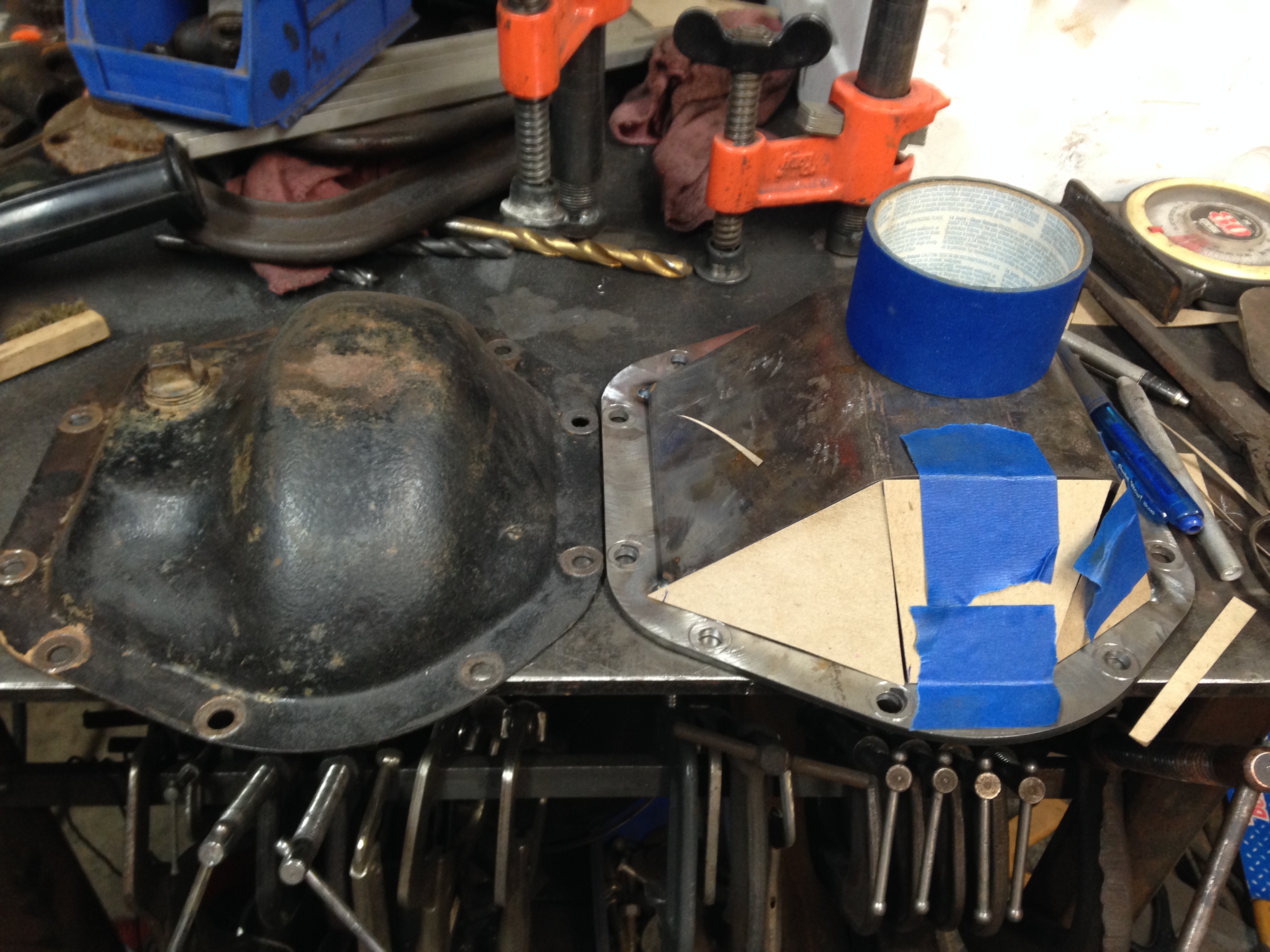 I started with using a thick cardboard to mock up the side pieces. I started with the center most piece to made sure I left enough room between the bolt holes and the weld area. During the test fitting of the outer ring I torqued the bolt and they left an impression of the outer diameter of the bolt head. This allowed be to better understand the distance needed to allow the bolt to still tighten up without hitting the weld. Once I had the shapes refined, I entered these into a CAD file I was able to create a G-Code program to cut the pieces.
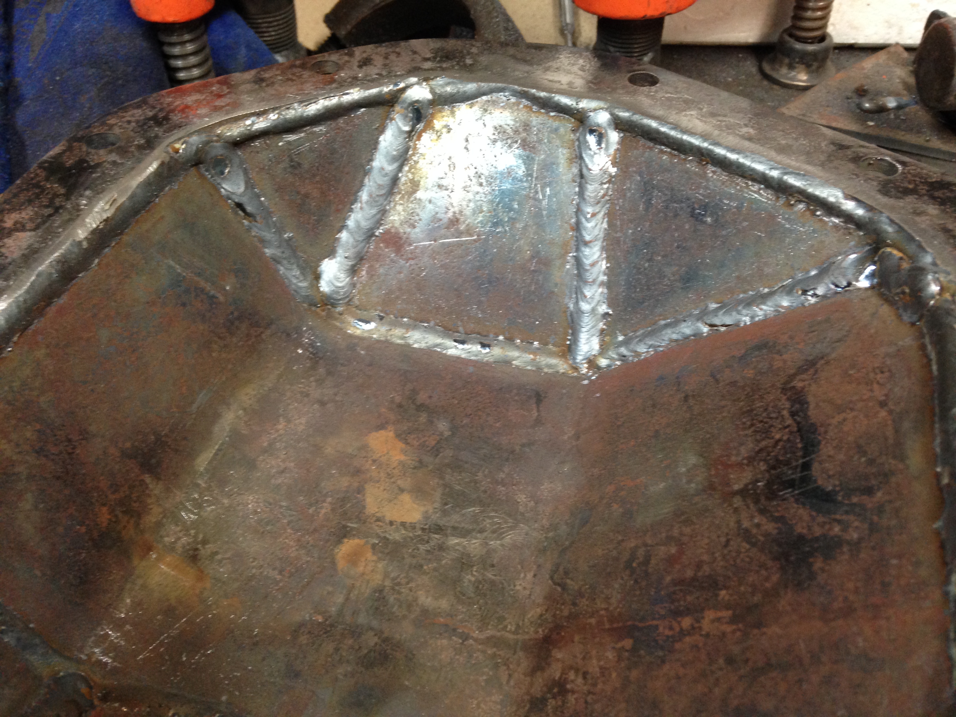
I then tacked all of the pieces, I test fit the cover to see if my measurements were close enough. Once I confirmed it still fit I re-installed the tie rod and turned the wheels to the stop in each direction. Now I was again able to turn sharp again.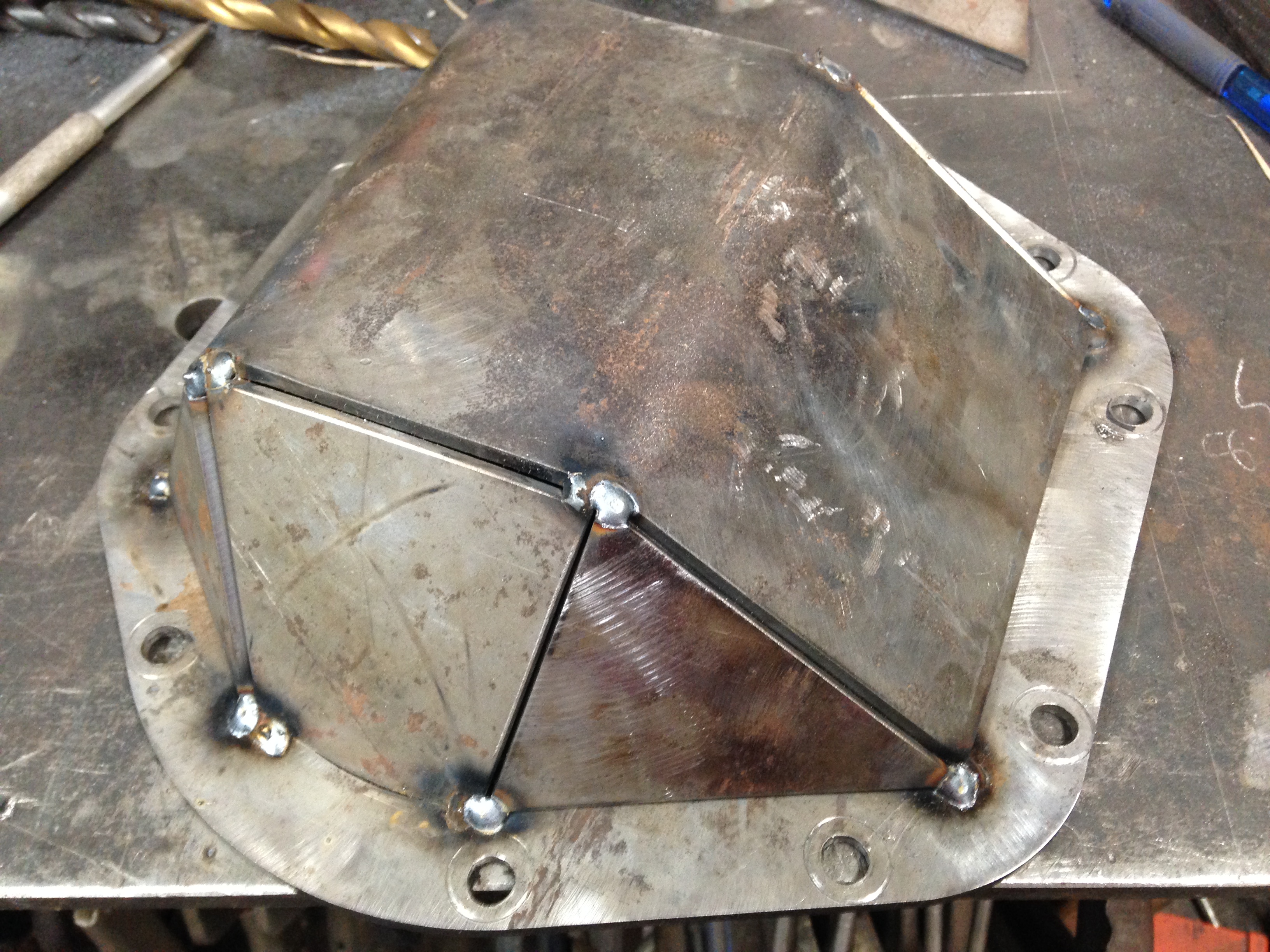 I started with tacking the center piece in, then moved to the two triangles. I repeated this on the second side. That is when I noticed that I had the main section about .05″ off to one side. Not a big deal, but it required me to grind the three remaining pieces to fit as precisely as needed to allow the bolts to clear the weld area.
 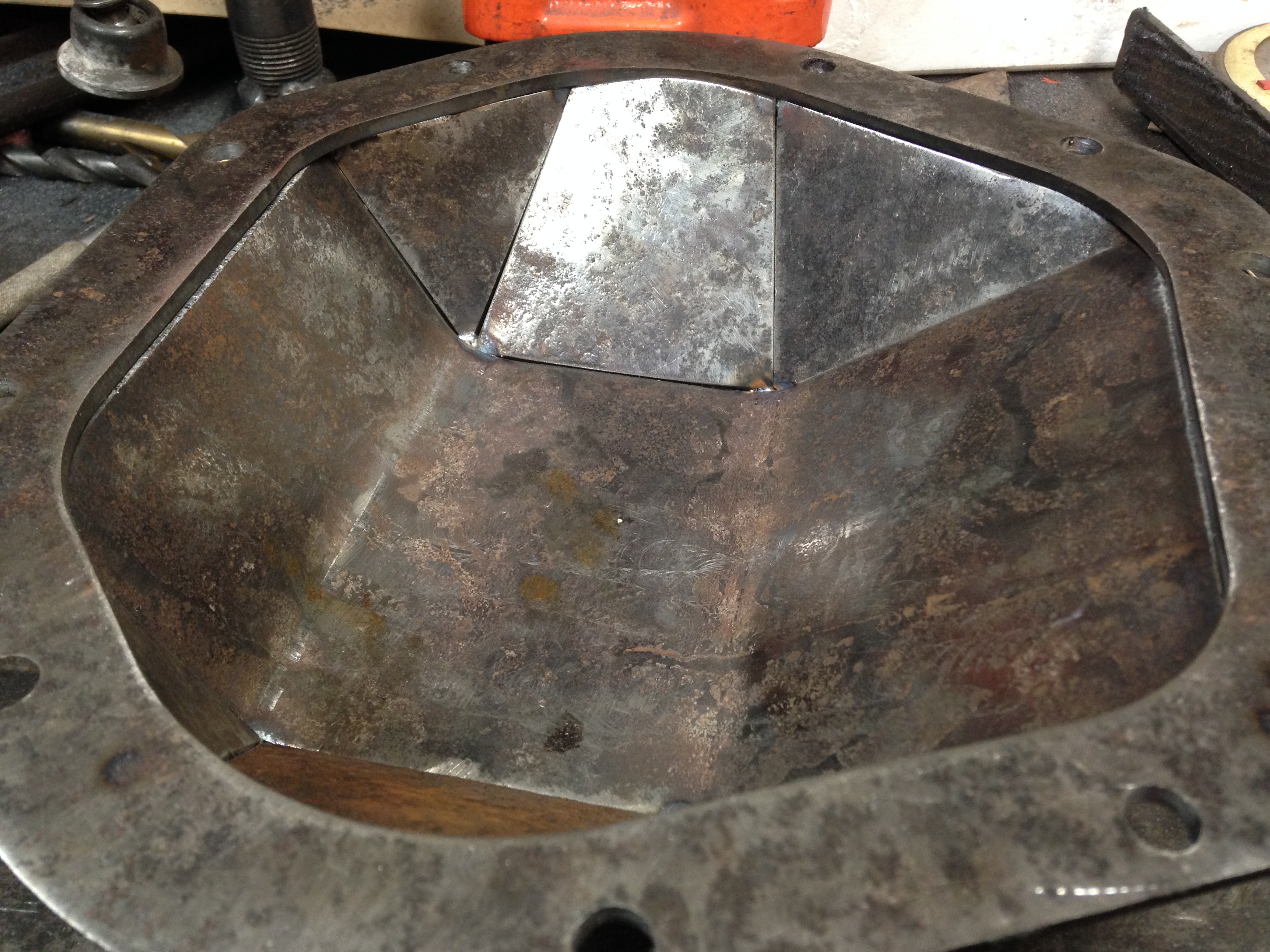 With the proper fitment was achieved, I was happy with the design of the cover.
I then proceeded to fully weld the cover inside and out to make it easier to clean. I started with the little section, making sure to go from on side of the cover to the other to keep the heat even over the cover and not to distort from too much heat input. This required me to stop and let it cool before finishing he outside and moving to the inside.
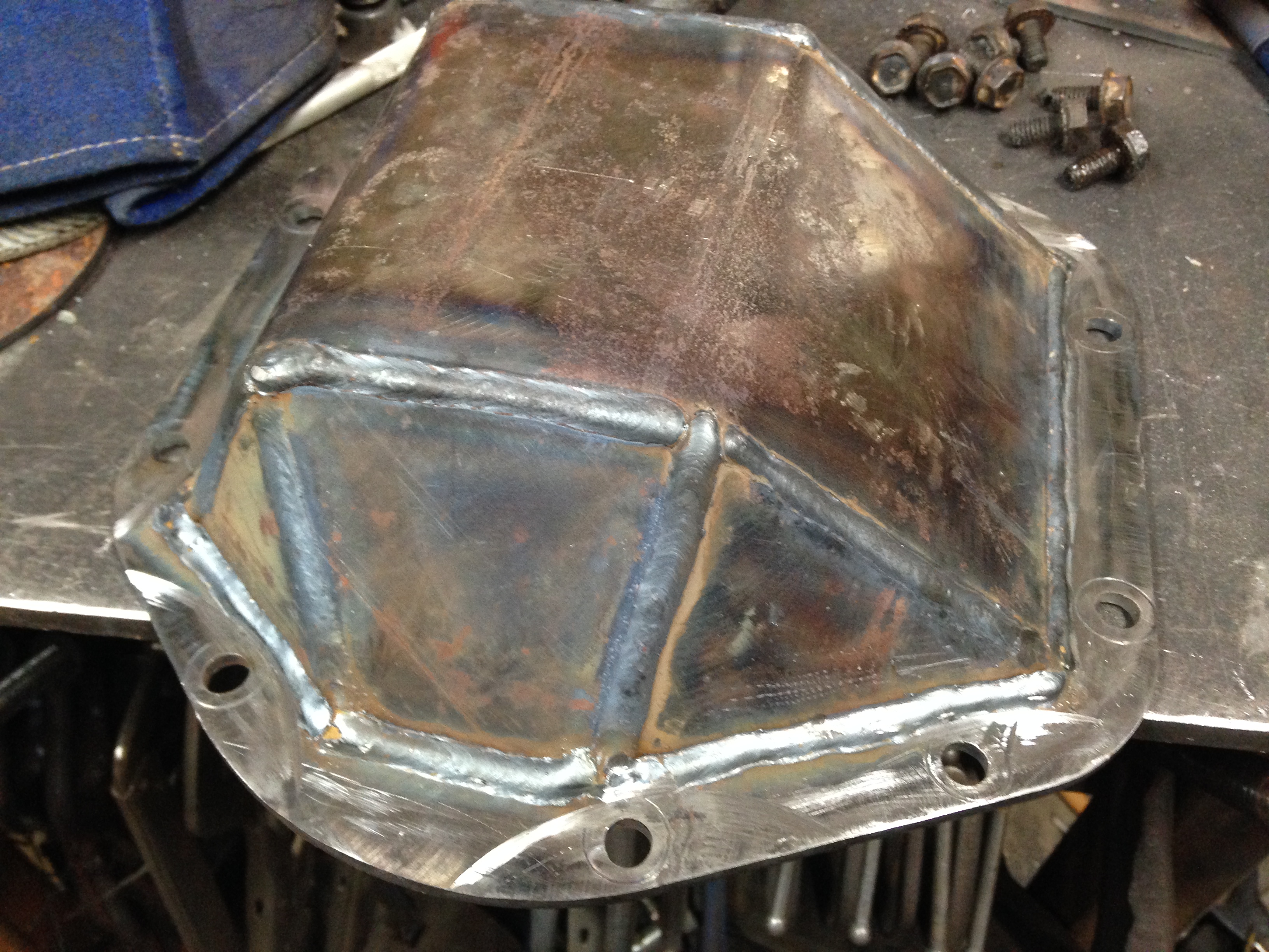
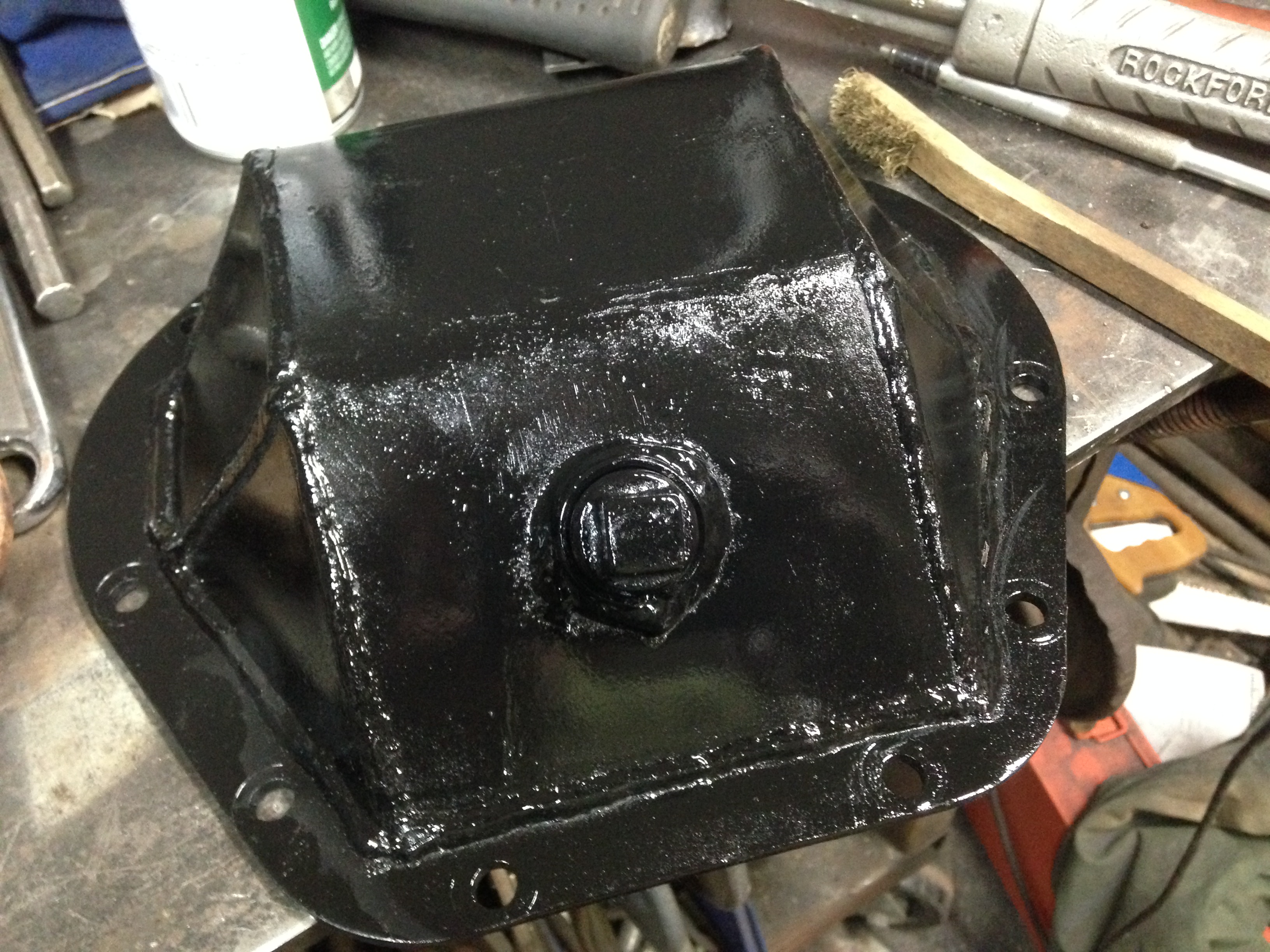
After I had the cover fully welded I then realized that I forgot the fill plug. This proved easier to remedy than I first thought. Seams it is easy enough to lay the cover down on the table and prop it up so that this needed surface was flat on table and cut a circle to allow the insertion of the weld bung for the fill hole. The last picture is the finished product. This should handle enough abuse that I can give it.